


Targets#
This page introduces the available targets for the testbed. In addition, we show how to
migrate to our hardware,
use the automatic node-ID patching, and
inform about possible pitfalls.
But first some words about the interface between targets and the observer. One of our design goals was to make features as neutral as possible. What does that mean? Using a feature like GPIO-Tracing shouldn’t have a meaningful impact on power-tracing, beside keeping the microcontrollers up for controlling the GPIO itself. Our level translators have a high impedance input and the traces itself have low capacitance for low energy losses during GPIO-usage. We went a step further and made sure that disabled features have even less of an impact. To continue with the GPIO topic - analog switches with a very low leakage current (in the nano-amp-scale) are used to separate GPIO traces from the observer if the feature is not in use. This way users with sensitive power-measurements can make sure that the results are least skewed.
Note
Shepherd Nova has a second (unused) target-port on each observer and our team is looking for ideas.
nRF52 with MSP430FR as FRAM#
The current hardware v1.3+ uses
Nordic nRF52840 - primary MCU with RF
TI MSP430FR5994 - secondary MCU with low-energy persistent memory
Abracon AB1805 - real-time clock
The main microcontroller for the user is the nRF52840. It is widely used in the community and offers a powerful radio. The MSP430 on the other hand offers a fairly large FRAM for intermittent computing. Using both controllers with custom firmware is possible. For ease of use we provide a firmware to use the MSP430 as an SPI flash storage. Users can also completely ignore the MSP430 and its features. If no firmware is selected, the testbed automatically disables the controllers by flashing a deep-sleep-firmware.
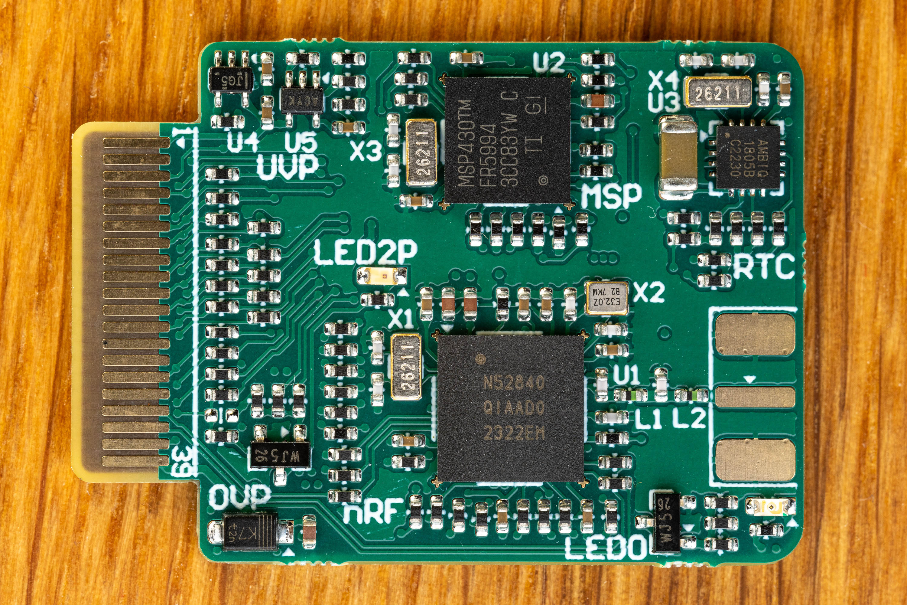
Photo of Target PCB v1.3e#
BOM, gerber-files and schematics are available in the PCB-Directory.
To quickly port your existing firmware to our hardware, we provide a handy mapping of shared pins below. For the initialization phase it may be beneficial to check the init-code of our example-firmwares.
Features#
freedom to use both MCUs as needed (just as radio or FRAM) or disable when not needed (deep sleep)
over-voltage protection for V_LV (max 3.9V)
under-voltage protection with hysteresis for nRF
one debug LEDs with separate supply for minimal impact on pwr-budget
one self-powered LED to “burn” energy
io pins not interfering with RF (nRF PS v1.6 page 578)
LEDs / UART similar to Riotee
nRF uses low voltage mode (PSv1.1 page 61)
16x GPIO shared to host, current-limited with 240R star-configuration (every participant has that resistor on its port to also keep data rates >10 MHz)
high & low power-good-signal (similar to Riotee)
SMA-port for external antenna
RF-Balun optimized for high output power (PS v1.8 ref circuit 7)
Firmwares#
nRF52#
nrf52_demo_rf: demo implementation for a simple node that sends BLE packets when energy budget allows it
nrf52_testable: watches all gpio and reports with UART messages (verification after assembly)
ensures that pcb is assembled OK and both MCUs are programmable and show basic functions
what is not tested: watchdog, FRAM, RF-Frontend (-> use rf-demo or rf-survey), sleep power consumption
nrf52_rf_test: sends out 1 BLE-Packet per second (verify with an app like
RaMBLE)nrf52_rf_survey: Link Matrix Generator - TX-Unit - sends packet with every possible P_TX, loops until stopped
nrf52_deep_sleep: practically turned off MCU with the lowest possible consumption
MSP430FR#
msp430_deep_sleep: practically turned off MCU with the lowest possible consumption
msp430_spi_fram: riotee implementation to use MSP as a flash storage
msp430_testable: switches on all shared gpio one by one (verification after assembly)
Custom Node ID#
Developers of communication protocols often rely on unique IDs in their network. While it might be possible to use the embedded UUID of the microcontroller itself, it has advantages to provide a custom ID for each target device. To avoid providing a dedicated firmware for each MCU our testbed offers to automatically patch generic firmwares before being flashed.
When an elf-firmware contains a SHEPHERD_NODE_ID, the variable will be patched with the actual target-ID before running the experiment.
This will be either the target-ID of the testbed (see floor-plan) or the custom ID (if provided).
See the proposed c-file for more information.
References#
Main Target-Repo & General Overview: https://github.com/nes-lab/shepherd-targets/
Target-Port of current Cape v2.5e: https://github.com/nes-lab/shepherd/tree/main/hardware/cape_v2.5e#target-port—cape-25d-this-revision
Main-Doku & general Overview (same as above): https://nes-lab.github.io/shepherd/external/readme_targets.html