Instance at TU Dresden#
Welcome to the first public deployment of the Shepherd Nova testbed! It is available for experiments all around the clock (24/7). This page describes the physical layout and wireless connectivity between nodes.
Physical Deployment#
Our testbed is located in the cfaed offices of the Barkhausen Bau at TU Dresden. It consists of 24 observer nodes that form a ring‑shaped network, largely determined by the building’s ventilation system. The many metal vents inside the ventilation system block radio signals, creating a realistic and challenging wireless environment.
Key Topological Features#
In addition to that ring-network, you can find or create the following topological features.
Dense cluster on the south side of the office-map - ideal for experiments that require many nodes with direct links
Bottleneck between offices II62 and II75 on the west side - useful for testing multi-hop routing
(elongated) U-shaped network can be created by disabling certain nodes or reducing transmit power
Floor Plan#
The map below from the Campus-Navigator shows the exact positions of the nodes.
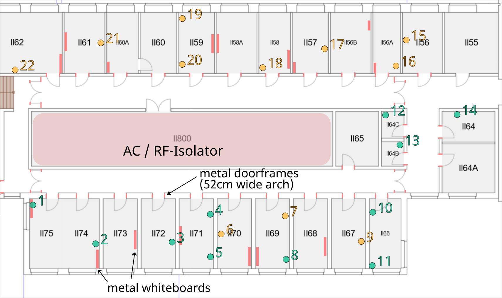
CFAED floor with marked node-positions. Most horizontal walls are concrete, while the walls between offices are drywall.#
Link-Matrix#
The link-matrix shows the measured RSSI (Received Signal Strength Indicator) values in dBm between every pair of nodes.
Tx⟍Rx     1     2     3     4     5     6     7     8     9    10    11    12    13    14    15    16    17    18    19    20    21    22    23    24
     +-----------------------------------------------------------------------------------------------------------------------------------------------
   1 |        -41   -53   -63   -63   -65   -79   -69   -85                                                                           -85   -71   -63
   2 |  -41         -51   -73   -55   -58   -78   -79   -86                                                                           -88   -69   -67
   3 |  -54   -51         -41   -39   -47   -65   -59   -73                                                                                 -69   -48
   4 |  -63   -72   -40         -44   -41   -54   -53   -67                                                                                 -42   -41
   5 |  -63   -55   -38   -44         -52   -54   -48   -73                                                                                 -47   -34
   6 |  -65   -58   -47   -41   -52         -48   -57   -54               -88                                                               -39   -45
   7 |  -80   -79   -66   -55   -55   -49         -41   -54               -85   -81                                                         -56   -51
   8 |  -69   -79   -58   -53   -48   -57   -40         -55               -83   -77                                                         -44   -47
   9 |  -86   -87   -74   -69   -75   -56   -54   -56                     -78   -74   -84                                                   -59   -75
  10 |                                                              -45               -84
  11 |                                                        -47
  12 |                                -88   -85   -83   -77                     -47   -83   -70   -71   -82   -77                           -85   -87
  13 |                                      -81   -78   -74               -48         -70   -75   -86   -89                                 -84
  14 |                                                  -84   -86         -83   -69         -71   -72   -88
  15 |                                                                    -71   -75   -71         -53   -57   -67   -72   -88   -85         -91
  16 |                                                                    -72   -86   -73   -53         -56   -71   -79   -73   -80
  17 |                                                                    -82   -89   -88   -57   -55         -55   -70   -69   -69   -87
  18 |                                                                    -76               -65   -70   -54         -64   -51   -66   -72
  19 |                                                                                      -72   -78   -70   -64         -43   -66   -61
  20 |                                                                                      -87   -72   -68   -51   -43         -69   -64
  21 |                                                                                      -85   -79   -69   -67   -66   -69         -48
  22 |  -85   -88                                                                                       -87   -73   -61   -65   -48
  23 |  -71   -68   -68   -41   -47   -38   -54   -43   -57               -84   -83                                                               -45
  24 |  -62   -66   -46   -41   -34   -45   -50   -46   -74               -86                                                               -46
This data helps you understand the network and configure custom topologies.
Rows (Tx) represent the transmitter
Columns (Rx) represent the receiver
Empty cells have no direct link
dBmis a logarithmic unit of power - higher values (closer to 0) are stronger links (e.g. -30 dBm is very strong, -90 dBm is very weak)
Updates are currently done manually - mainly after changes in deployment. It is planned to offer weekly scans in the future while also keeping the history available. A collection of past measurements and network-layouts is available here.
Impressions#
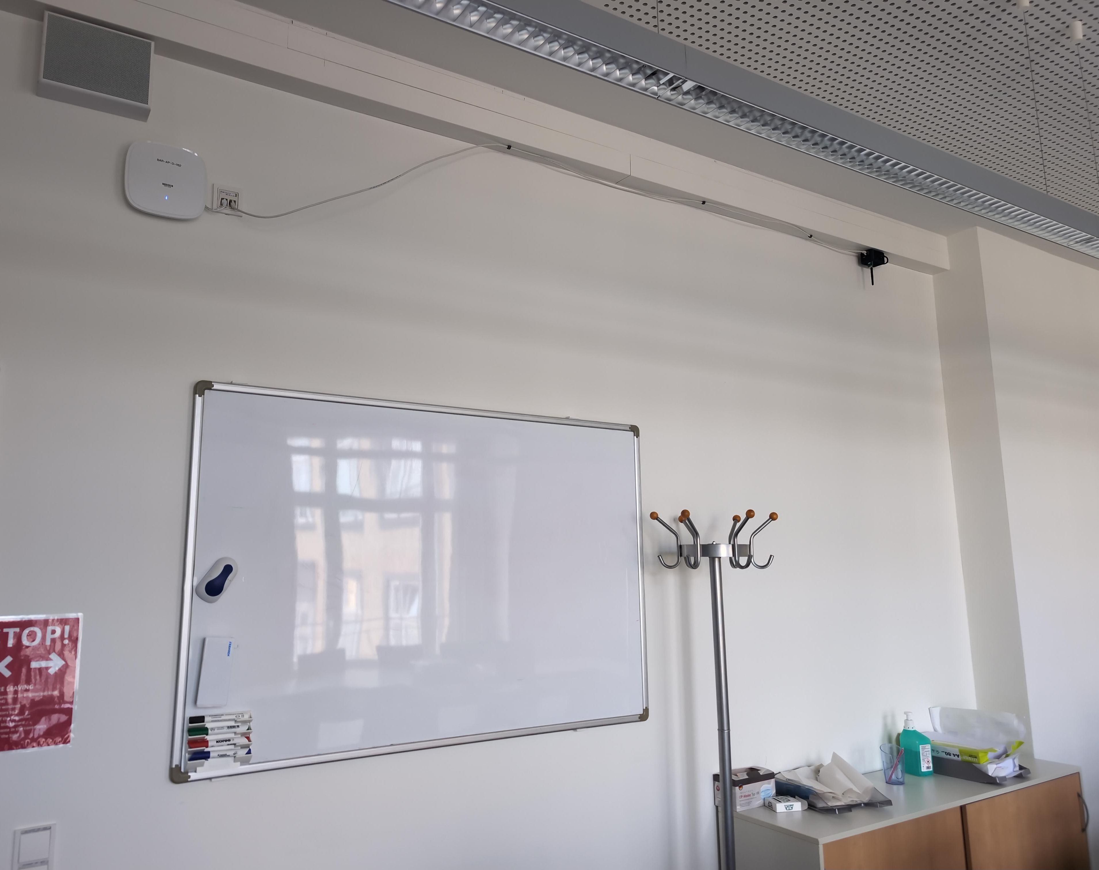
Observer node deployed in conference room II62. It is mounted under the ceiling-duct and connected and powered via ethernet.#
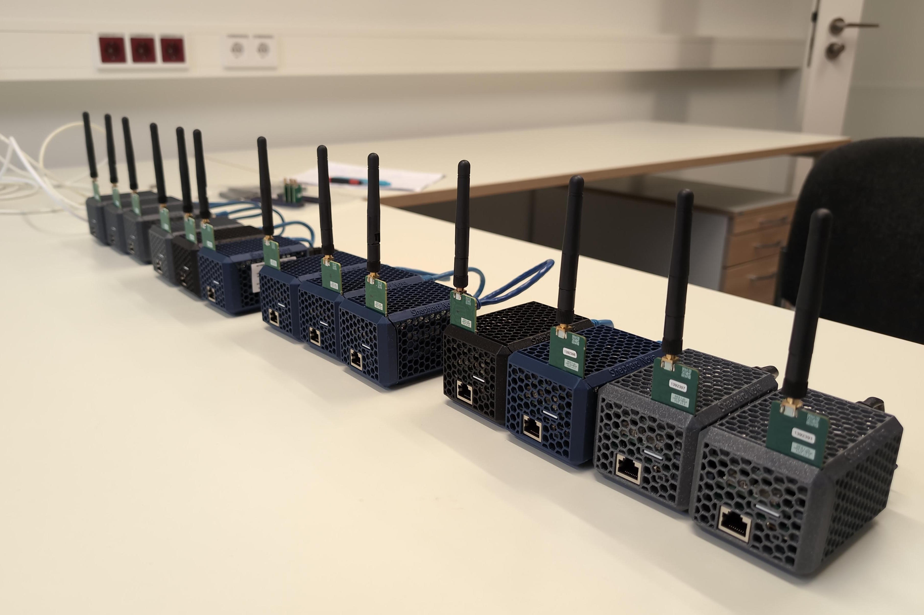
Observer nodes are assembled and tested - right before deployment.#